Copyright 2003, 2013 Nikolas S. Boyd. All rights reserved.
Software is an unique form of literature. Software is useful, usable fiction. Software can be designed to resemble the structures of, relationships between, and behaviors of things that exist in our real and imagined worlds. Thereby, people can use software to solve real world problems and improve the quality of their lives. While software has enormous plasticity and can be molded to fit our real world needs, software remains figurative and fictional, figments of our literate imaginations.
As fiction, software is entirely and thoroughly metaphorical. Metaphors pervade every element and aspect of software, from the lowliest variable name to the largest of enterprise architectures. Software is so steeped in metaphors that we often overlook the extent and nature of these metaphors. Like fish in water, software developers often do not perceive the medium that surrounds us: our natural languages, natural conceptual models, and the natural and linguistic metaphors we use every day in our software designs. Even so, software developers borrow ideas, terminology and organizational structures from every field they encounter and every problem they solve.
This essay explores a wide variety of these metaphors in hopes of awakening a greater awareness of them in software developers and in hopes of making their acknowledgement more common and explicit in the general practice of software development.
Cognitive science studies conceptual systems, especially how the brain and the mind operate. While a relatively new discipline, cognitive science has made some rather startling discoveries in a short time. In their groundbreaking book Philosophy in the Flesh,1 George Lakoff and Mark Johnson explain many of these discoveries. Cognitive science has discovered that:
|
We acquire our primary metaphors during our earliest years. Our sensorimotor experiences structure our subjective experiences. During our earliest years, we learn hundreds of primary metaphors that neurally associate distinct conceptual domains. Subsequent to these periods of conflation, we separate these domains, differentiating the metaphorical sources from their targets. Complex metaphors are later formed by conceptual blending from these primary metaphors. Widespread (universal) conventional conceptual metaphors develop from common experiences. Some of the primary metaphors we commonly acquire include the following:
|
Given that our subjective and cognitive experiences are rich in metaphor, it should not surprise us to find that our software designs are also full of metaphors. The next few sections explore the most essential software metaphors, beginning with those derived from algebra and the elements of software design.
In their consideration of Where Mathematics Comes From,2 Lakoff and Núñez suggest that metonymy plays a crucial role in our thinking about algebra:
Consider how we understand the sentence "When the pizza delivery boy comes, give him a good tip." The conceptual frame is Ordering a Pizza for Delivery. Within this frame, there is a role for the Pizza Delivery Boy, who delivers the pizza to the customer. In the situation, we do not know which individual will be delivering the pizza. But we need to conceptualize, make inferences about, and talk about that individual, whoever he is. Via the Role-for-Individual metonymy, the role "pizza delivery boy" comes to stand metonymically for the particular individual who fills the role - that is, who happens to deliver the pizza today. "Give him a good tip" is an instruction that applies to the individual, whoever he is.
This everyday conceptual metonymy, which exists outside mathematics, plays a major role in mathematical thinking: It allows us to go from concrete (case by case) arithmetic to general algebraic thinking. When we write "x + 2 = 7," x is our notation for a role, Number, standing for an individual number. "x + 2 = 7" says that whatever number x happens to be, adding 2 to it will yield 7.
Some of the expressive and representational foundations of software have their origins in algebra. So, just as we use metonymy as a cognitive base for our understanding of algebra, the same metonymy serves as a basis for our thinking about software elements and components, especially as we later explore the metaphors of object-oriented software design. But first, let's examine software elements themselves and the metaphors from which they derive.
In Elements of Software Science,3, 4 Maurice Halstead identified the essential elements that serve as the basis for studying and measuring the structure of software.
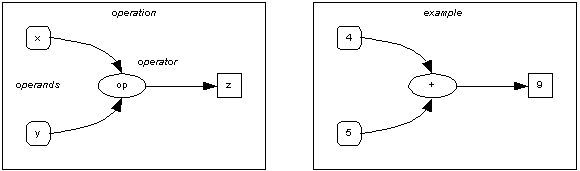
Given an implementation of the algorithm in any language, it is possible to identify all of the operands, defined as variables or constants, that the implementation employs. Similarly, it is possible to identify all of the operators, defined as symbols or combinations of symbols that affect the value or ordering of an operand. From the identification of operators and operands, it is possible to define a number of countable, hence measurable, entities that must be present in any version of the algorithm. These properties are the basic metrics from which the relationships of software science have been obtained.
On the basis of these elements (operands and operators), their derived relationships, and experimental validation, Halstead developed early quantitative measures for several important software qualities, including vocabulary size, program length, program volume, program level, difficulty, effort, and even an error hypothesis. For the purpose of this discussion, we will focus on the elements themselves and the metaphors that arise from their usage.
Software elements reflect the underlying hardware elements found in most conventional (von Neumann) computers, especially the processor and memory. Computer memories store values. Computer processors operate on these stored values. The software elements and the hardware elements correspond to each other as follows:
|
Operations compose algebraic formulas from operands (the algebraic terms) and operators (the algebraic functions). Computer processor operations embody algebraic functions, especially simple binary formulas like addition, subtraction, multiplication, division, logical and, or, exclusive or, etc.
Processor operations can be encoded as instructions with numerical values. These instructions can be aggregated into programs, stored in computer memory, and used to guide a processor through its computations. This was one of the key insights and innovations offered by computer pioneer John von Neumann on behalf of the entire EDVAC team:5 program instructions can be stored in memory and treated as data values. Conventional computer processors read their program instructions from memory, decode the instructions, and perform the specified operations. Each processor operation has a discrete, finite encoding as an instruction. So, each instruction represents a processor operation and requires some finite amount of memory storage. Instruction sequences are aggregated into programs stored in a segment of computer memory. The processor traverses these instruction sequences, performing the operations encoded by the instructions that compose the program.
Another benefit results from this organization of instruction sequences. Just as complex algebraic formulas can be composed from simple formulas, complex operations can be composed from sequences of (simpler) operations. So, a sequence of processor operations can be stored in memory and referenced as a reusable operational unit (a function). Then, sequences of function references can be organized into more complex operations. Conversely, during software design, large complex systems and services can be decomposed into subsystems and components, which are further decomposed into complex operations, which are further decomposed into simpler operations, which are ultimately decomposed into sequences of (primitive) processor operations.
Computer operating systems manage basic computer resources, including the scheduling of processor usage (time) and the allocation of memory space. A computer processor threads its way through the code stored in memory. So, instruction execution threads have become a basic kind of resource managed by modern operating systems.
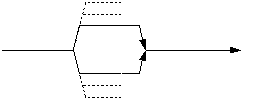
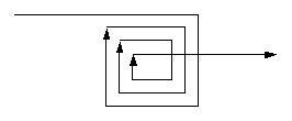
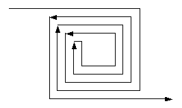
Basic code patterns can be likened to stitch patterns. Basic code patterns include sequence, selection, iteration, and recursion. It's interesting to note that iteration and recursion are patterns of repeated execution often described as loops. Thus, code loops can be likened to the repeated knotting of threads sometimes used in weaving.
Figure 2. Thread Patterns |
Just as basic code patterns exhibit small scale structural patterns, functions and methods can exhibit larger scale structural patterns. These larger scale patterns of function and method invocations can be likened to the textures that appear in some kinds of woven products.
Computer processors are now generally fast enough that they can usually switch between and effectively trace several execution threads "concurrently" according to human perception. Thus, execution threads can be likened to the straight warp on a loom, around which intricate patterns of code are entwined and intertwined to produce a fabric of data as results.
The Software Weaving Metaphor
Loom —> Operating System Fibers, Yarns, Threads —> Processor Execution Threads Stitch Patterns —> Basic Code Patterns Knots —> Loops Textural Patterns —> Function Patterns, Template Methods Fabrics, Carpets —> Function Results, Global Program States
While other organizational techniques play important parts in modern software design theory and practice, functional decomposition and functional composition still remain essential. Similarly, structural decomposition and structural composition are essential organizational techniques for operands (data). The composites that result from these organizational techniques provide the basis for two of the most fundamental software metaphors: trees and layers.
Software is composed of organized fragments: constants, variables, expressions, statements, signatures, functions, methods, classes, etc. Just as trees have a branching structure that exhibits fractal self-similarity on multiple levels, so do software structural and functional composites. Also, due to their dependencies, composite functions can be organized as layers. When the relationships between composite functions are depicted graphically, their tree-like structure becomes apparent, along with their layers.
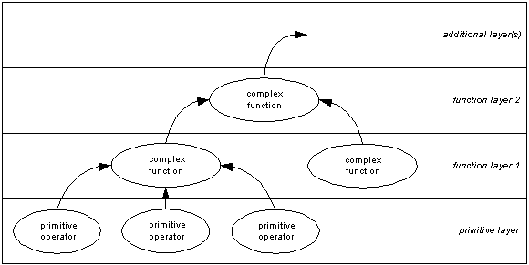
There are some other implications that follow directly from the von Neumann software model. Both primitive operators and complex functions have signatures: zero or more arguments and their types, zero or more results and their types. Complex function signatures serve as the boundaries, the interfaces, between distinct, functional software layers. As complex functions are implemented using sequences of operations, these operation sequences are the implementations of the complex functions. It follows that:
Thus, while new functional additions rarely impact existing implementations, interface signature changes often entail changes to the implementations that depend on them. However, hiding implemention details behind interfaces can limit the propagation of such implementation changes. Many of the techniques for organizing software into components are strongly motivated toward limiting the propagation of change. But, all of these organizational techniques are predicated upon these essential separations.
Software development has natural cycles of expansion and consolidation. During periods of expansion, software systems grow in size as developers add new features and embed code to measure and manage new quality concerns. However, such expansion has natural limits brought on by various kinds of software quality degradation: defects, duplication, ambiguity, excessive complexity, excessive coupling, design impurities and incoherence. Developers often characterize their experiences with software quality degradation anecdotally as a kind of rot or decay. As we shall see in subsequent sections, developers often use such colorful biological metaphors to describe software.
Occasional (if not regular) periods of design consolidation are the neccessary antedote for software quality degradation. Such consolidation usually involves refactoring: the intentional (usually incremental) improvement of software designs. Because design improvements can often be done incrementally, consolidation (especially via refactoring) can be interleaved with expansion. Aggressive (even merciless) refactoring helps maintain overall software quality during periods of software growth. Also, making design improvements incrementally distributes and amortizes their costs over the periods of expansion.
Software methods (statement sequences), statements, and expressions are like mathematical (algebraic) formulas. Like formulas, code can be factored. Factoring algebraic formulas reduces their apparent complexity through the identification and isolation of common terms (factors). Likewise, code can be factored by identifying and isolating redundant expressions, statements, statement patterns, and data usage patterns. Code redundancy, density and general inscrutability have been characterized (colorfully) as stench and (more formally) as impurities. New code often introduces design impurities. Impurities are a natural consequence of software growth. Six kinds of basic code impurities were identified by Halstead:3
| complementary operations |
the successive application of two complementary operations to the same operand. |
|
| ambiguous operands |
an operand name refers to different things at different places in a program. |
|
| synonomous operands |
two different names refer to the same thing. |
|
| common subexpressions |
a specific combination of terms is used more than once without being named. |
|
| unwarranted assignment |
a specific combination of terms is named, but used only once. |
|
| unfactored expressions |
a specific combination of terms can be isolated from an expression. |
|
|
Refactoring improves software designs through incremental changes that: simplify the organization of the code, clarify the intent of the code, increase its intelligibility, make it easier to maintain, or easier to introduce new features. Some additional software impurities were identified by Kent Beck and Martin Fowler (as bad smells) that warrant refactoring:6 |
||
| duplicated code |
an expression or a statement sequence appears repeatedly. |
|
| long method |
long methods decrease intelligibility and increase maintenance difficulty. |
|
| large class |
a class has too many instance variables or too many static/class variables. |
|
| long parameter list |
the same (or similar) long parameter list is used by several methods. |
|
| divergent change |
a class is changed in different ways for different reasons. |
|
| shotgun surgery |
several related classes must have little changes each time one of them changes. |
|
| feature envy |
a method relates more to a class other than the one in which it is located. |
|
| data clumps |
several data elements appear together repeatedly as variables and/or parameters. |
|
| primitive obsession |
several methods operate on some related primitive data element(s). |
|
| switch statements |
some method(s) contain switch statements that operate on the same value. |
|
| parallel hierarchies |
extending a class in one hierarchy entails extending one in another hierarchy. |
|
| lazy class |
the design includes a class that does very little. |
|
| speculative generality |
the design includes some abstract class(es) that do(es) very little. |
|
| temporary field |
an instance variable is set only in certain circumstances. |
|
| message chain |
some client code contains a long chain of object structure navigation messages. |
|
| middle man |
some class delegates half or more of its behaviors to another class. |
|
| inappropriate intimacy |
some classes are far too intimate with each others' private parts. |
|
| alternative interfaces |
some classes do the same (or similar) things with different method signatures. |
|
| incomplete library class |
a library class is missing some needed features. |
|
| data class |
some class(es) have fields and accessor methods, but no other behavior. |
|
| refused bequest |
some subclass(es) don't want or need all of their inheritance. |
|
| (deodorant) comments |
some comments are used to mask bad smells in the code. |
|
Most algorithmic programming languages structure software similarly. Software components are composed from software elements and from references to software elements and other software components. Algorithmic programming languages differ largely in their focus on various higher level capabilities: logic, functions, objects, events, concurrency, resource sharing, network distribution, etc.
Table 1 (below) provides a representative list of software components and elements and indicates their relationships and contents. The indicated software organizational model primarily reflects that of the Java programming language,7, 8 but it captures many of the salient features of algorithmic languages, generally. Note that such languages generally have four organizational levels: elements (operands and operators), operations (expressions, statements, methods), components (types and classes), and composites.
|
|||||||||||||||||||||||||||||||||||||||||||||||||||||||||||||||||||||||||||||||||||||||||||||||||||||||||||||||||||||||||||||||||||||||||||||||||||||||||||
Table 1. Common Software Structures |
|||||||||||||||||||||||||||||||||||||||||||||||||||||||||||||||||||||||||||||||||||||||||||||||||||||||||||||||||||||||||||||||||||||||||||||||||||||||||||
It's worth noting that nearly all software components and elements in Table 1 must be given names so that they may be referenced by other components. Component and element names are critical design decisions. Good names enrich our conversations and organizational memory. Poor names obstruct our ability to construct, share, effectively operate on, and maintain software. Ideally, names used in software designs are natural and appropriate to the context of their usage. Natural names:
Within the overall conceptual framework (and bias) provided by a programming language, software component and element names express the metaphors used by software developers. To foster, establish and durably retain software intelligibility, development teams need to agree on naming conventions for software components and elements.
Most software development experts emphasize the importance of names, but fail to explain how good names are discovered and constructed. There are few works in the extant literature that explicitly address the naming of software elements and components. However, Kari Laitinen has focused much of his early work on this and provides many useful suggestions regarding naming conventions in his collected papers on disciplined natural naming.9 Natural names deepen the metaphoric linkage between code, design and the concepts we're attempting to embody therein.
Software performs repetitive (often boring) processes mechanically and autonomously (without human intervention). This is one of its primary purposes - to free people from having to perform menial information processing chores. So, some portions of software behavior are repetitive. These repetitive behaviors reflect on the fact that the data being processed often has some repetitive organization and/or structure. Because of the prevalence of repetitive data, software libraries often provide standard equipment (components) for managing collections of repetitive data.
Equipment Summaries and Metaphors Array A simple repetitive organization of (often similar) elements. An arrangement - a set of elements arranged in an order. Bag Allows element duplication without imposing any ordering constraints. A disorderly collection of (often different) elements. List An ordered collection of (often similar) elements. A simple series of things that may be counted or enumerated (numbered). Map Maps some keys to their corresponding (associated) values, supporting keyed element lookup. A dictionary used to find things. A figurative graphical map used to locate things via correspondence between their positions on the map versus their positions in the world. Pool An homogenous collection of shared, reusable resources. A readily available (fluid) supply. Queue An ordered collection of elements with first in, first out (FIFO) removal behavior. A waiting line, especially of things (or people) to be serviced or processed. Set Prevents element duplication without imposing any ordering constraints. A disorderly collection of (often similar) elements. Stack An ordered collection of elements with last in, first out (LIFO) removal behavior. An orderly pile or heap whose topmost elements must be lifted and removed to gain access to its bottommost elements. A vertically arranged set of elements that are kept in place by the effects of gravity. Tree Simple binary or multiway structures that have repetitive branching (self-similar, fractal) substructures like those of trees.
Sometimes the processes performed by software are not only repetitive, but they also require the use of resources that are shared (and may entail waiting) or whose usage may have some comparatively large latency (as when accessing a peripheral). To maximize the amount of processing that can be accomplished within any given span of time (throughput), operating systems and some programming languages and platforms provide mechanisms for sharing the computer processor between multiple concurrent processing tasks. However, these concurrent independent threads of computation often need coordination. So, a variety of standardized thread synchronization mechanisms have been developed and incorporated into programming languages, libraries and operating systems.10
Equipment Summaries and Metaphors Barrier A cyclic barrier prevents (bars) further processing (forward motion) of some concurrent threads until the entire set of coordinated threads have arrived and met (joined) at the barrier. After the coordinated threads have met at the barrier, they are again released to continue their further independent processing. Channel A mechanism used to convey data between a pair of concurrent threads (often in a synchronized manner) similar to way that a canal (or a cane reed) channels water. Deadlock A condition wherein two concurrent threads are each waiting for the other to release a lock it has acquired. Each has locked out the other, leading to each blocking the other from further processing. Fork / Join Creates and coordinates a pair (or more) of concurrent threads. One thread branches off from the other, and may eventually rejoin it at some later time. Future An object blocks a thread requesting a value until that value has been produced, at some future time. Lock A mechanism associated with a shared resource which, when acquired by a thread, locks out any other concurrent threads interested in acquiring the same resource until the original acquiring thread has released (unlocked) it. Some locking alternatives include more permissive access for certain kinds of threads. For example, concurrent threads which only inspect a shared resource without changing it may do so safely without risk of interference. Monitor A monitor watches (over) a shared resource and prevents simultaneous access by multiple concurrent threads. Mutex A kind of lock whereby multiple concurrent threads mutually exclude each other from accessing a shared resource. Semaphore Indicates (signals) that a shared resource has been acquired. In the world, semaphores are visual signals, usually conveyed with a pair of flags.
Values (quantities) without measures (qualities) are meaningless. Measures without dimensions are ambiguous (at best) or utterly confusing (at worst). However, the variables used in software designs usually convey only value and measure. The variables themselves carry only values. Thus, the variable names bear the responsiblity for communicating intent, i.e., the intended role, purpose, or use of the value held by each variable. Unfortunately, the measure dimensionality associated with a value is often lost or relegated to the documentation associated with the variable definition. Sometimes, the measure dimensionality associated with a value will be included in the variable name, especially when the measure dimensionality is simple.
However, variable names that represent measures with complex dimensionality seldom include the dimensionality because they would cause the name length to be excessive. For example, we might find the following line of code in a Java program.
double signalStrength; // measured in decibels per milliwatt (dB/mW)
The need to include dimensionality in measurement representations has led to the development of libraries that combine values and dimensions (usually as object-oriented classes). These libraries also provide mechanisms for combining measures of different dimensions and converting between measures of similar dimensions, e.g., combining length and time to produce velocity, and converting between distances measured in feet versus meters. The Units Specification (JSR 108)11 for the Java platform is an example of one such effort to develop a comprehensive measurements library. TODO: I'd really like to include references to additional quantity library efforts, e.g., for C++, C, etc.
The object-oriented approach to software design has become one of the dominant models (if not the dominant model) for organizing software. The object metaphor is the foundation of the object-oriented approach to software design. This metaphor likens software components to real-world objects, be they physical or conceptual. Software objects organize knowledge and behavior into distinct deliverable, composable, and reusable units (components). As a practical matter, organizing software as objects helps keep data in close proximity to the functions (methods) that operate on the data. However, this metaphor benefits from many aspects of our understanding of real world objects, including their qualitative and quantitative aspects, their relationships, and their taxonomies and ontologies. The metaphor used to organize software as objects has the following structure:
The Software Object Metaphor �
Real World Physical or Conceptual Object —> Software Object Real World Object Behaviors —> Software Object Behaviors Real World Taxonomies and Ontologies —> Software Object Classification Hierarchies Real World Object Qualities (and Quantities) —> Numeric-Valued Instance Variables Real World Object Connections and Associations —> Object-Valued Instance Variables
Three (largely biological) organizational metaphors serve as the foundations of the object-oriented approach to software design: encapsulation, polymorphism, and inheritance. The following three sections will examine each of these organizational metaphors in detail.
Software objects can be likened to living cells. Each object protects its internal contents with a semi-permeable membrane of public methods. The public methods provide a boundary or interface that separates the contents of an object from its environment. Just as a cell membrane transports materials into and out of a cell, the public methods transport data into and out of an object. The public methods control how and when the supported operations are used by other external objects. Thus, public methods surface object states and ensure that quality constraints are properly maintained.
The Software Encapsulation Metaphor �
Cell —> Software Object Cellular Exterior —> External Client Objects Cellular Membrane —> Public Methods Transport Data into and out of an Object Cellular Interior —> Protected Data (and Methods)
In addition to the basic cellular metaphor, software encapsulation entails some metaphors that relate to the visibility of software component internals. These metaphors have traditionally been expressed in terms of boxes that offer various levels of visibility:
The Software "Box" Metaphors �
Opaque "Black" Box —> Interface Publication Only - No Visible Software Internals Diffuse "Grey" Box —> Software Exposes Some Internals or Provides Some Plugability Clear "White" Box —> Open Source - Entire Implementation Open to Inspection
Software objects can be likened to organisms. Each object has a morphology (shape and behavior), with both internal (usually hidden) structure and external (exposed) structure. So, like organisms, populations of objects exhibit morphological similarities and differences.
Sometimes, organisms with identical functions implement those functions with different mechanisms, e.g., compare the respiratory mechanisms of mammals and fishes. Certain populations of objects exhibit a similar kind of polymorphism, when they have some apparently identical, externally visible function(s) in their interfaces with substantially different internal implementations.
The externally visible similarities and differences between objects leads to additional biological metaphors: classification and taxonomy. Just as populations of organisms can be classified according to their morphological similarities and differences, so too can objects. In fact, most object-oriented programming languages support this possibility directly with their programming models and syntax, i.e., with classes.
Just as biologists organize the plants and animals into taxonomies according to their presumed natural relationships, software developers organize object classes into taxonomic class hierarchies according some criteria of similarities and differences. Alternatively, object classes can represent certain kinds of knowledge, and they can be organized into (descriptive) ontological hierarchies that also resemble biological taxonomies.
The Software Morphology Metaphors �
Organism Populations —> Object Populations Organism Internals ("Guts") —> Object Internals Organism External Surface —> Object Interface Organism Classifications —> Object Classifications (esp. Classes) Organism Taxonomies —> Class Hierarchies and Ontologies
Just as organisms (especially people) have familial relationships, software object classes also show familial relationships by virtue of their classification hierarchies. Just as children inherit observable traits from their parents, objects exhibit the traits they acquire by virture of their classifications and the organization of their classes into hierarchies.
Classification hierarchies allow software developers to organize classes according to their similarities and differences. This approach supports differential class design, incremental implementation and reuse. Classification hierarchies provide software developers with two complementary inheritance mechanisms: interface inheritance and implementation inheritance.
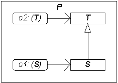
Of the two, interface inheritance is the more important (necessary and therefore primary) mechanism. Classes (inherently) implement types. So, classes always expose interfaces. Consequently, subclasses inherit the interfaces (types) of their superclasses (and supertypes) transitively through to their root superclass(es). In 1988, Barbara Liskov12 first described a design principle with respect to the substitutability of object types: subtypes should be substitutable for their supertypes, or more formally:
If for each object o1 of type S there is an object o2 of type T such that for all programs P defined in terms of T, the behavior of P is unchanged when o1 is substituted for o2 then S is a subtype of T.
Implementation inheritance achieves reuse through inherent (implicit) composition. However, implementation reuse can also be achieved through explicit referential composition. But, object class designs frequently couple interfaces with their implementations. So, most object-oriented programming languages support implementation inheritance with explicit syntax as a design and modeling convenience.
Some of the earliest pioneers of object-oriented software development likened objects to collaborative agents. This view refines the object metaphor further and makes it anthropomorphic, likening the interactions between objects to those exhibited by human teams. This explicitly anthropomorphic view of software was formalized as Responsbility-Driven Design (RDD) in the late 1980's. Wirfs-Brock, et. al. discussed this approach to software development in Designing Object-Oriented Software.13
Object-oriented design encourages a view of the world as a system of cooperating and collaborating agents. Work is accomplished in an object-oriented system by one object sending a request to another to perform one of its operations, reveal some of its information, or both. This first request then starts a long chain of such requests.
Objects may be modeled on inanimate or even conceptual entities in the real world, but within their systems they act as agents, just as we do within ours. It may sometimes paradoxically seem as if objects know more than their real-world counterparts. After all, in the real world telephones do not dial each other, nor colors paint themselves, without human agency. Whereas the systems of daily life require human agents to make things happen, objects are the agents within their own systems.
The responsibility-driven approach captures design decisions with Class-Responsibility-Collaborator (CRC) cards. Traditionally, (3.5" x 5.0") index cards have been used to capture and organize design decisions regarding the naming of classes, their heritage relationships, their assigned responsibilities, and their collaborations with other classes. Here's an example excerpted from the design of a Document System described in Designing Object-Oriented Software.13
| Responsibilities —> |
|
<— Collaborators | ||||||||||||||||||||||||
Collaborators are correlated to the responsibilities of the roles in which they participate. After the roles, classes and responsibilities have been captured, the specific interactions between objects are designed, often using linguistic metaphors (see those described below). The metaphor of software objects as collaborators has the following structure:
The Software Object Collaboration Metaphor �
Collaborators —> Objects Collaborator Roles —> Class Names Division of Labor between Roles —> Class Responsibilities Responsibilities for Knowing and Doing —> Class Methods Responsibilities for Ensuring (Quality) —> Class and Method Constraints Requests for Knowledge and Action (with Guarantees) —> Object Messages
Just as natural language distinguishes quality, behavior and knowledge concepts with descriptive adjectives, verbs and nouns, responsibilities can be distinguished as qualities, behaviors and knowledge. The names we give these qualities, behaviors and knowledge can be derived from the descriptive adjectives, verbs and nouns that appear in natural language problem descriptions.
| Responsibility Schema | ||||||||||||||||||||||||||||
| � | ||||||||||||||||||||||||||||
|
In object-oriented solutions, interactions always occur between a pair of objects: a client and an implementation of a service, which are typically modeled (even if only partially) with interfaces. The client makes a request of a service. The request might be for some information known to the service, or it might be for the service to make some kind of change while maintaining some quality guarantees. Thus, clients come to rely on the correct behavior of the services on which they depend.
Given the importance of correctness in overall software quality assurance, the precise definition of service quality guarantees has become an important practice and supported by software programming systems to a greater (or lesser) degree. The practice of formal interface specification between collaborating objects, along with their associated guarantees, has further developed the collaboration metaphor into a metaphor of software service contracts.
The Software Service Contract Metaphor �
Contract Participants (Parties) �� �> �� Collaborating Objects Contractual Obligations �� �> �� Collaborator Responsibilities Client Guarantees �� �> �� Method Preconditions Supplier Guarantees �� �> �� Method Postconditions and Class Invariants Mutual Benefits �� �> �� Exchanged Values + Maintained Qualities
Just as human collaborators work with each other, objects also collaborate to produce results. The collaboration metaphor can be extended, and the design of object communications can be structured to resemble human communications. Object interactions (messages) can be designed to resemble natural language sentences, especially sentences that use transitive imperative verbs.
The sentential message metaphor has the following impact on object method signature design. The message receiver becomes the subject of a sentence. The message request (an intention revealing method name) becomes the verb of a sentence. The message arguments become direct and indirect objects in the sentence, with names that indicate their thematic roles. The structure of this metaphor can be summarized as follows:
The Sentential Message Metaphor �
Sentence —> Object Message Subject (esp. Agent) �� �> �� Message Receiver Verb / Phrase (esp. Transitive Verb) —> Message Request Sentence Format (esp. SVO) �� �> �� Method Signature Direct and Indirect Objects —> Method Arguments Thematic Roles (Agent, Patient, ...) —> Method Argument Names Prepositions —> Method Argument Delimiters (Smalltalk)
This metaphor motivates several recommendations regarding the best practices of object-oriented method and interface design.
Interface designers should consider what will be most convenient for the client.
Method signatures should be intelligible to and expressive for clients.
Methods should be named after what they accomplish rather than how they accomplish it.
Methods should generally be small so that they
Some object-oriented programming languages make it especially convenient to fulfill the recommendations entailed by this metaphor. In Smalltalk, this includes the use of prepositions to delimit method arguments, which makes method signatures especially expressive and intelligible. The following statement from a client method provides an example of how Smalltalk supports these service method signature design practices.
| channel send: message in: envelope to: recipient. |
Software solutions often devote large percentages of their volume to handling errors and exceptions that can arise during usage, even though such situations may occur only infrequently, as "edge cases." Given the importance of correctness, Wirfs-Brock and McKean devote an entire chapter to this consideration in Object Design. 14
Depending on the criticality of the software in question, the consequences of failure can vary from inconveniences, to monetary losses, to loss of life. So, it's important to appropriately gauge the possible kinds of failures and their potential consequences, and design appropriate kinds of responses into a solution, including both automated recovery (where possible) and human interventions (where not).
Much of a service's quality depends on trust and the trustworthiness of its collaborators. From the point of view of a service, this applies especially to its clients and the other collaborators on which it depends, including the availability of any requisite resources it needs. It's good to consider whether and how services can degrade gracefully, perhaps providing different levels of service quality depending on the availability of resources (or their lack).
Close collaboration promotes trust over paranoia. A service design can establish a trust boundary that includes specific collaborators, and thereby eliminate extraneous pathologies and redudant quality checks. A service can also include quality checks on its required external resources, that are applied at appropriate moments as a kind of built-in self test, especially at startup.
As a further refinement of the notion of contracts, services can declaratively specify constraints on their collaborators (esp. their clients) and on the data exchanged with them. With such constraints, at least certain kinds of quality checks can be automated, either using a compiler (as with type constraints), or within the context of a data validation framework, where constraints can be checked at runtime using the services of the framework. Thus, the service itself can be freed from carrying bulky "boilerplate" code that would otherwise be required by it to ensure its proper operation.
One way or another, it's up to a service to ensure that it has the resources it needs, that its clients supply it with good data, and use the service in accordance with its design. Breaches of its contract(s) must be enforced vigorously in order to ensure its quality guarantees.
The Software Service Contract Metaphor (Extended) �
Contract Participants (Parties) �� �> �� Collaborating Objects Client Guarantees �� �> �� Type and Data Constraint Conformance Supplier Guarantees �� �> �� Data Quality and Quality of Service Adherence to Terms �� �> �� "Contract" Constraint Conformance Breach Consequences �� �> �� Exceptions + Error Values
Software often has many structural and lexical levels and layers. Overall, software has an organizational structure that exhibits fractal, semi-repeating, structural patterns: systems, hierarchies, objects, fields, methods, statements, expressions, terms. These complex structural aspects of software have led to the development of several organizational techniques, including structured, functional, logical, object-oriented, and aspect-oriented approaches to software design.
All of these approaches have been practiced for many years with various degrees of success and popularity among software developers. Consequently, their practitioners have observed that repetitive organizational patterns (both structural and behavioral) arise in software. These software design patterns are practical solutions to specific kinds of design problems that arise in the context of specific sets of problem forces and factors that need to be balanced and resolved. Some investigators have developed coherent collections of related design patterns as pattern languages.
An extensive body of literature for software design patterns has grown out of the recognition that software design patterns need to be shared. Many software industry researchers have adopted design pattern literary forms similar to that pioneered by the building architect Christopher Alexander. A Pattern Language15 organizes the various spatial design patterns that Alexander and his associates discovered in their experiments with building architecure. A Pattern Language is hypertext in a book. Each spatial design pattern in the pattern language has links to other design patterns, including patterns that are larger in scale, as well as those that are smaller in scale. The span of scales ranges from large to small, from regions to cities and towns, communities and neighborhoods, buildings and homes, interiors and rooms, decorations and ornamentation. Throughout the book, the design patterns emphasize natural integration with surroundings, human living, and human concerns.
In 1996, Christopher Alexander was invited and gave a keynote speech16 at the ACM Conference on Object-Oriented Programming Systems, Languages and Applications (OOPSLA). He challenged the conference attendees to consider the consequences of their unique position and the opportunity to participate in the creation of living structures in the world. He suggested that software developers may be able to create structural design (CAD) software that produces designs informed with natural patterns and living, harmonious structure.
While software developers may eventually be able to create programs that can help architects generate and design such living structures, there is another challenge that is perhaps a bit closer to home. Software design patterns help developers design software. They provide developers with a common language of software design, improving communication and thereby increasing our understanding and productivity.
But, there is a set of software design challenges to be considered that serves as an analog to that posed by Alexander. How can software be made more humane, both internally and externally? How can our design and coding techniques be improved to produce designs that are intelligible, coherent, and maintainable? How do we transcend the merely technical benefits of design patterns to achieve the human-scale benefits of usability, intelligibility, and coherence? One of the means towards these ends would seem to involve more explicit acknowledgement and usage of metaphors in software design. The software design patterns and pattern languages that relate to software structure and behavior are rich in such metaphors and offer steps in this direction.
In 1995, Wolfgang Pree identified a set of primitive design elements for constructing software design patterns and introduced the term metapatterns17 to describe these primitives. Metapatterns are composed of primitive behavioral and structural design elements: behavioral composition with hook and template methods, and structural composition with inheritance and attachment (coupling), including recursive structures (structural composites).
Dynamically bound methods make the behavioral aspects of design patterns possible. Hook methods are dynamically bound methods that implement the hot spots in a design. Hook methods can be abstract methods, regular methods, or template methods. Template methods implement the frozen spots in a design. Template methods define generic control flows over hook methods and between collaborating objects.
Sometimes, hook methods and template methods are unified in a single class, but they are often separated into a hook class that contains some hook methods and a template class that contains some template methods. Each hook class (H) and template class (T) can then be composed together in various combinations along with inheritance and with either or both classes being abstract or concrete. The basic metapatterns that result from these various combinations include the following:
| Metapattern | T : H reference(s) | T >= H inheritance |
| unification | none (0) | none (T = H) |
| each template T refers to . . . | ||
| 1:1 recursive unification | 1 hook instance (H) | none (T = H) |
| 1:N recursive unification | N hook instances (H*) | none (T = H) |
| 1:1 connection | 1 hook instance (H) | none (T not = H) |
| 1:N connection | N hook instances (H*) | none (T not = H) |
| 1:1 recursive connection | 1 hook instance (H) | the template extends the hook class (T > H) |
| 1:N recursive connection | N hook instances (H*) | the template extends the hook class (T > H) |
Metapatterns can be used and combined to generate software design patterns, which can then be combined and instantiated to generate software designs. Thus, software designs can be fabricated by weaving together these elementary design elements: hook and template methods, plus hook and template classes. And like a fabric, when software designs are examined, they reveal their design textures.
Inspired by the works of Christopher Alexander, the so-called "Gang of Four" offered Design Patterns18 to the software development community in 1995. While not quite a coherent pattern language, this collection of design patterns does exhibit relationships between the various patterns. The pattern format resembles that used by Alexander, with differences appropriate to software designs. Since then, the Pattern Languages of Programming (PLoP) conference has met annually and systematically increased the literature of software patterns. The following table lists some of the software design patterns that have become popular since their advent in the literature.19, 20, 21, 22, 23
| Pattern | Metaphor(s) and Summaries | |
| Factory Method | Factories and Manufacturing - factory methods create new objects | |
|
Object-oriented programming entails the creation of class instances (instantiation). But, exactly what kind of object will sometimes be determined dynamically. The determination may involve some parameters. A Factory Method provides a way to defer the decision until runtime, and the determination may include some parameter value(s). Factory Methods sometimes use Builders for complex object construction. An Abstract Factory usually has several Factory Methods. |
||
| Abstract Factory | (aka Kit) factory objects create new objects of various kinds | |
|
Object-oriented programming entails the creation of class instances (instantiation). No object is an island, so related parts often require production as assemblies. But, implementations depend on interfaces. So, rather than couple object assembly users directly to specific part and assembly classes, the specific part and assembly classes are hidden behind abstract interfaces and the manufacturing processes for instance families are hidden within an Abstract Factory. Each Abstract Factory usually aggregates some Factory Methods. Each Abstract Factory is usually implemented as a Singleton. Some Abstract Factories create new instances using Protoypes. |
||
| Builder | Builders and Construction - complex objects often have several parts and their construction often has several steps | |
|
No object is an island, so related parts often require production as assemblies. Sometimes these assemblies have replaceable and optional parts. So, rather than expose the construction details of the assemblies and their potential variations, the construction process(es) are the responsibility of a Director, which directs a Builder in the construction of its product assemblies. Builders often construct Composites. |
||
| Singleton | Uniqueness and Individuals - sometimes a class has only one (individual) instance | |
|
Singletons ensure that they are unique by preventing clients from creating new server class instances. Instead, each Singleton server class creates and caches its sole instance and supplies that instance to its clients when requested. Each Façade is usually a Singleton, as is (usually) each Abstract Factory. |
||
| Prototype | Metonymy and Cloning - an instance stands in place of a class | |
|
A prototypical instance serves as a template for creating other instances. New instances are initially copies of the prototype. This may reduce the number of classes, or otherwise simplify the creation of instances, especially for dynamically resolved classes. The Prototype pattern may be a suitable alternative to Builder and a complex parallel hierarchy of Factory classes. |
||
| Null and Void | No Thing and No Way - the absence of an object needs representation | |
|
Java and C++ provide void to indicate the absence of a method result. Java uses null to indicate the absence of an object, while Smalltalk uses nil. The absence of an object can be tested and an appropriate behavior chosen, or an appropriate exception raised. |
||
| Null Object | (aka Exceptional Value + Meaningless Behavior) sometimes a design needs to do nothing gracefully | |
|
Object-oriented frameworks often need a way to do nothing gracefully or otherwise provide a default behavior in the absence of explicit specification or configuration, especially when such behaviors are replaceable. So, it is often useful to include an object (type) that serves as a placeholder with a default behavior, often doing nothing. A Null Object will often be more useful than having to test for Null and responds accordingly. |
||
| Composite | Composition and Components - fractal, tree-like structures often have repetitive (recursive) structural similarities at various levels | |
|
Whole-part hierarchies are often modeled using tree-like composite structures. Composites allow clients to uniformly manipulate and process both individual Components and their assemblies (composites), often using Visitors. Often, some of the Components will need Decorators to supply additional and optional behaviors transparently in conformance with some protocol(s) standardized by the basic Component interface. Sometimes a Component knows about its extended behavior(s) supported via pluggable Strategies. |
||
| Decorator | Decoration and Ornamentation - add new responsibilites to components transparently without subclassing | |
|
Within a whole-part hierarchy, some of the Components may need additional or optional behaviors. Given that the interface for a basic Component has been standardized, a variety of Decorators can be derived from Component and thereby transparently composed with other Component. When the common protocol supported by all Components is engaged (e.g., visual components draw themselves) and passes throughout the composed hierarchy, the Decorators supply their additional behavior before (or after) passing control to their subcomponents. |
||
| Visitor | Visitation and Inspection - complex structural compositions often need to be traversed and inspected | |
|
Whole-part hierarchies often have some basic behaviors for structural navigation and some uniform, abstract behaviors, usually as Composites. However, some kinds of manipulation may not be appropriate to embed in the Component classes. Instead, the Composite provides a uniform mechanism for visiting each kind of Component in the structural hierarchy. |
||
| Strategy | Replaceability and Transparency - a family of interchangeable algorithms that offers a common signature | |
|
Traditionally, polymorphism (a common abstraction with different implementations) has been coupled to inheritance. The Strategy pattern separates polymorphism from inheritance. The Strategy pattern defines a (narrow) functional abstraction with a single signature and multiple (usually distinct) implementations. The Java programming language directly supports this kind of abstraction with its ability to define an interface as well as a class. |
||
| Façade | Faces and Interfaces - software components have usable faces (interfaces), some of which serve as façades | |
|
Subsystems often need to expose a simple interface for client usage. The Façade pattern offers a way to hide the details of how the parts of a subsystem interact and relate to each other. Each Façade will usually be implemented as a Singleton. |
||
| Facet | some components surface multiple faces for use by different (kinds of) clients | |
|
Sometimes the responsibilities of a class are better surfaced separately because different kinds of clients make use of the different services. For example, inspection and mutation operations may be relevant only to disparate kinds of clients. In fact, it may be not be appropriate for all clients to have access to all services. In which case, the separation of these services from each other may be required. |
||
| Proxy | Representation and Surrogation - some objects stand in for others | |
|
Direct object presence may sometimes have unacceptable costs. Proxy objects mitigate these costs in several ways. A remote proxy serves as a local substitute for an object in a different address space. A virtual proxy manages the costs of working with expensive objects. A protection proxy controls access to a protected object or its protected operations. A smart reference performs additional actions when the object of fronts is accessed. |
||
| Bridge | Connection and Transportation - an abstraction is separated from its implementation(s) | |
|
Just as bridges transport vehicles, software bridges transport data across narrow (or yawning) chasms that separate disparate (sub)systems. The Bridge pattern allows for the (relatively) independent evolution and extension of an abstraction and its implementation(s), especially where they separate different software layers. A Bridge will often have some kind of Proxy for its clients to use. |
||
| Adapter | Compatibility and Adaptation - disparities between similar systems with incompatible interfaces can be overcome using adapters | |
|
When integrating classes from disparate class libraries, some of the classes from one may have need of the services offered by some class(es) from the other. The Adapter pattern provides a means for integrating some otherwise incompatible class(es) into a (sometimes new) system. It also offers a way to design reusable class library (often a framework) that explicitly supports the (pluggable) integration of some unforeseen classes in the future. |
||
| Gateway | Adaptation and Transformation - a set of related services that map and exchange data between two layers (or tiers) | |
|
Where the Adapter pattern rephrases the services offered by an interface, the Gateway pattern transforms (adapts) the data passing through an interface established to separate a pair of software layers (e.g., between a presentation layer and a business object layer, or between a business object layer and a persistence layer). A Gateway interface often captures the use-cases for operating on some kind(s) of objects, especially the create, read, update, and delete (CRUD) cases. |
||
| Pool | Fluidity and Availability - shared and reusable resources often need a common place to be found | |
|
Some reusable resources are collected into a pool. The pool contains the reusable resources and a protocol for resource usage requires the return of the resource to the pool after its use. This may be likened to a pool of water with a recirculating pump: the water travels out of the pool for a time, but ultimately returns to the pool after its travels. Saturation. When all available instances of a reusable resource type are being used, the resources have become saturated. For example, when all the threads from a thread pool are actively servicing requests, the threads have become saturated with requests, and no more requests can be serviced. Management.24 Resources that are pooled often have a protocol for correct resource acquisition, usage and return. Some critical resources must be returned to the pool or subsequent failures will result. So, some resource pool designs impose the correct resource usage lifecycle on their clients. Thus, clients are allowed access to and use of a resource only under management supervision. The resource management interfaces and implementation ensure that clients respect the entire resource usage lifecycle by taking care of resource acqisition and release for clients. |
||
| Flyweight | Brevity and Immutability - small plentiful objects can be pooled and reused | |
|
While the cost of creating a small object may be small, if too many are created and then always retained or always discarded, the performance and storage costs may mount to the point where they are prohibitive. The Flyweight pattern caches a plentiful set of small, sharable, immutable objects (the flyweights) in a pool and allows them to be used in multiple contexts simultaneously. Clients never create flyweights directly, but only ever obtain them from a Factory (or a Pool or Registry). |
||
| Registry | Identification and Registration - identifiable objects often need a common place to be found | |
|
Some finite populations of uniquely identifiable instances have long lifetimes, and may even be backed by a persistent object store. The object class may provide access to a specialized registry for holding objects of this class. The registry provides a single place in which to register and locate the members of the class. The registered instances are found by mapping each unique member identifier to the identified member. The registered instances are typically stored in a Pool or a Map. |
||
| Repository | persistent domain objects often benefit from separate, specialized maintenance | |
|
The Repository pattern extends the Registry pattern specifically for persistent domain objects. Each Repository houses and manages a specific kind of domain object. Each Repository hides its underlying data source and the details of how its domain objects are mapped and stored in its underlying backing store (typically a relational data store). Repositories often accept Query requests for domain objects. |
||
| Model | Essence and Meaning - essential semantics separated from presentation, distribution and persistence concerns | |
|
Each problem domain has some essential elements that may be identified and named, which are collectively described as a semantic model or a domain model. These essential domain elements have attributes, constraints and behaviors. However, many benefits accrue from separating non-essentials into other software layers, including those concerned with application, presentation (see View and Controller), distribution and persistence (see Repository). It is often beneficial to separate domain elements from how they are applied and used in some specific application context. Such separation produces a domain model and a separate application model. The application model describes how the information and operations supported by the domain model elements surface for use, often through Views and Commands. |
||
| View | Transformation and Presentation - information often needs to be collected, filtered, formatted, and presented | |
|
Views collect, filter, format, and present information from their underlying domain Model objects. Just as database Views aggregate and filter information from different database tables, application Views (aka Data Transfer Objects) and view fields can be used to aggregate and filter information from domain objects. Interface Views present information through interface components (aka Widgets). Interface Views may be separated from, but are often combined with Controllers to manipulate the elements of a domain Model. |
||
| Controller | Mutation and Manipulation - objects may be manipulated through their usable faces | |
|
Controllers manipulate the elements of a domain Model, often using Commands to represent operations on the Model objects. Controllers usually serve as Listeners for interface Events, translate these into Commands that operate on the Model objects, and then notify the interested View(s). The View(s) are often Observers of the Model objects, which then refresh themselves with updated information collected from the Model objects. |
||
| Mediator | Intermediation and Translation - interactions between objects can be separated out so that the participants need not know each other explicitly | |
|
When several objects know and interact with each other, the complex connections and interactions may be difficult to understand. The participants may be too intimate with each other and may benefit from decoupling. The Mediator pattern separates out and centralizes the interactions so that the participants need not know and interact with each other. Instead, each participant knows a Mediator, and the Mediator knows each participant. The Mediator forwards requests and changes from their originating participants to target participants as appropriate. |
||
| Observer | Notification and Observation - interested parties can be notified when an object changes and then observe what changed | |
|
Subjects accept (register) interested Observers, who subscribe for change notifications. Subjects publish notifications to interested (registered) Observers without having to know them intimately. Each Observer (has the opportunity to) inspect the Subject whenever it receives a change notification. Complex applications and application families often benefit from combining the Observer pattern with the Mediator pattern. |
||
| Listener | observers interested in specific kinds of changes listen for them | |
|
A Listener has a much more focused interest than that of an Observer. While an Observer receives notifications of object changes, a Listener receives notifications of specific kinds of Events. Some Event notification mechanisms even offer more explicit kinds of notification filtering, often based on Event contents (in addition to kinds). |
||
| Command | Repeatability and Auditability - disparate requests can be captured as objects, recorded, applied, and rolled back | |
|
The Command pattern represents a service request as an object, often converting a verb phrase to a noun phrase through nominalization. By converting service requests to Commands (or transactions), they can be parameterized, made repeatable, reversible, and recordable. A persistent log of changes captured as Commands can be replayed after a crash. Commands are often derived from a common abstraction, so that the set of Commands can be easily extended, and so that they can be handled in a common way. The Command pattern resembles the Query pattern. |
||
| State | Lifecycle and Transitions - behavioral changes throughout a lifecycle can be represented with objects | |
|
Some objects have complex lifecycles with several states, and they change their behavior depending on their active state. Operations on these kinds of objects often have embedded state tests to distinguish the operative behavior appropriate to each state. The State pattern turns each state into a concrete class derived from a state abstraction, and the State pattern distributes the state-specific behaviors to these concrete state classes. The State pattern can be viewed as a variation of the more general Strategy pattern. |
||
| Query | Inquiry and Selection - specific requests for information can be represented with objects | |
|
The Query pattern represents an information request (esp. selection criteria) as an object, often converting a question into a noun phrase. By converting questions into Queries, they can be parameterized, made distributable and recordable. A persistent log of questions captured as Queries can be audited. Queries are often derived from a common abstraction, so that the set of Queries can be easily extended, and so that they can be handled in a common way. The Query pattern resembles the Command pattern. |
||
| Event | Changes and Notifications - specific kinds of change occurrences can be represented with objects | |
|
The occurrence of a change can be represented and captured with an Event object, often including information relevant to the interested Event Listeners. Related kinds of Events can be organized into classification hierarchies. Different software layers often have their own distinctive kinds of Events. Interface Events usually include information from a peripheral, e.g., mouse events include mouse position and button states, while keyboard events include the key pressed on the keyboard. Application events are usually custom indications of selection changes. Domain events if surfaced by the domain Model indicate changes in domain objects. |
||
| Policy | Decisions and Policymaking - sometimes decision making needs to be replaceable | |
|
The Strategy pattern can be further refined. When a Strategy provides a decision, whether boolean or case-oriented, it can be said to specify a Policy. The Policy pattern abstracts decision algorithms in the same way that the Strategy pattern abstracts algorithms that produce other kinds of results. |
||
Large software systems are often likened to buildings, especially with respect to their architecture. As with buildings, issues of construction, utility, habitability, style, unity, coherence, integrity, and integration often arise with large (esp. enterprise-wide) software systems. As the practice of software architecture has evolved, it has borrowed many terms from building architecture: foundations, platforms, ornaments, structures, frameworks, scaffolding, etc.
The Software Architecture Metaphor �
Building Platforms �� �> �� Software Platforms Building Foundations �� �> �� Software Foundations Building Frameworks �� �> �� Software Frameworks Building Rooms and Furnishings �� �> �� Software Components Building Halls, Stairways, Elevators �� �> �� Software Connectors Building Ornaments �� �> �� Software Decorators and Convenience Methods Building Quality Attributes �� �> �� Software Quality Attributes Building Architecture �� �> �� Software Architecture
Alistair Cockburn has likened software development to mountain climbing,25 but sometimes it's more like spelunking. Both are team sports, both involve vertical challenges of ascent and decent, but they oppose each other in the order and character of these endeavors. Mountain climbing involves ascent into open, airy space, followed by descent to ground level. Spelunking involves descent into close, dark space, followed by ascent back into the light. The vertical challenge metaphors are equally apt for software development: climing up vs. spelunking down and building vs. discovery.
The study of large (esp. legacy enterprise) software systems may also be compared with archeology: digging through layers of design and code, recovery and preservation of valuable artifacts, discovery of ossified and deteriorating legacy code (with attendant, so called "bit rot").
Over several years, David Garlan and Mary Shaw have surveyed software architectural styles and offered many insights regarding their structure (design) and formal characteristics. One survey they published jointly in 199426 enumerates several of the most common architectural styles. Each architectural style solves certain kinds of problems well and therefore has a natural fitness for certain problem frames or combinations of problem frames.27
| Architectural Style | Problem Frame(s) |
| object-orientation | workpieces + commanded behavior + information display |
| event driven | required behavior + information display |
| pipes and filters | transformation |
| table driven interpreters | transformation + workpieces |
| repositories (blackboards) | information display + required behavior (esp. with distributed agents) |
| software layers | multi-frame problems |
As architectural styles continue to be analyzed and characterized in terms of their quality attributes,28 it seems likely that a more systematic process for architecture selection based on qualitative fitness criteria versus quality requirements in formal problem descriptions will be developed.
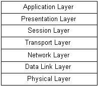
As noted previously, software designs often have layers that arise from the composite structure of functions and methods. However, large software systems often exhibit another kind of layering, one that separates concerns and distributes responsibilities across the layers. The block diagram in Figure 5 shows a traditional depiction of the International Organization for Standardization (ISO) Open System Interconnect (OSI) seven layer model (protocol stack) for computer network communications.29
The application layer is responsible for data exchanges between distributed applications, including such activities as file transfers, message delivery, etc. The presentation layer is reponsible for data translation (as between character encodings), cryptographic encoding and decoding, and data compression. The session layer is responsible for the lifecycle of data exchanges, including connection initiation, synchronization, data transmission, and disconnection. The transport layer is responsible for proper packet buffering, connection multiplexing and demultiplexing, and connection reliability. The network layer is responsible for packet routing, packet size reconciliation, and (often) packet statistics. The data link layer is responsible for data quality, ensuring that data exchanges are free of errors, duplications, etc. The physical layer is responsible for moving data across a physical medium between two connected end points.
|
Figure 5. Open System Interconnect Layers |
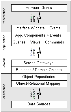
Figure 6. Enterprise Application Layers and Tiers |
In many cases, there are also physical divisions as well as logical divisions. Such divisions are characterized as tiers when the functional layers are spread across and hosted on multiple distinct computers in a network. The block diagram in Figure 6 shows one of the possible organizations of such layers and tiers. Figure 6 shows a fairly typical modern enterprise application architecture, including a client tier consisting of web browsers, an application tier, a business service and domain tier, and a relational database tier. Distributed across these physical tiers are several functional layers, including those responsible for producing a human interface, exchanging information between the human interface and the service interface, implementation of business services and business objects, a repository for persistent objects and for mapping persistent objects to and from a relational data store.
The separation of components and objects into distinct layers often depends on whether and to what degree an application architect is familiar with the kinds of layers that are possible, as well as how many tiers the application requires. Often the decision regarding tiers depends on the nature of the application, its anticipated usage patterns, the performance characteristics of the application, and the performance characteristics and configuration of the available equipment on which the various application layers will be hosted.
The Software Layer Metaphor �
Geological Strata —> Software Implementation Layers Geological Strata Interfaces —> Software Interface Dependencies Geological Strata Count, Depth, and Kind —> Software Layer Count, Depth, and Kind
As noted previously, elementary software operations compose operands and operators to produce results. Also, complex operations can be composed from the results of more primitive operations. These kinds of functional compositions have also been characterized as data flows.30 Data flows into operations (as operands) and out of operations (as results).
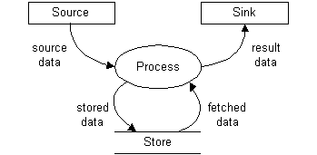
As a general model, data flows often provide a convenient mechansim for solving problems that fit into a data transformation problem frame.27 Complex functions can be decomposed and depicted using notations like that shown in Figure 7. When complex functional composites are analyzed, decomposed, and diagrammed, they often appear as large data flow networks with many ovals and many arrows connecting them. Large data flow network designs can be likened to complex pipelines and other civil engineering works. Thus, one of the commonly articulated software architecture styles26 is rooted in metaphors of fluid networks, pipes and filters.
The Data Flow Network Metaphor �
Fluid —> Data Spigot, Spring —> Data Source Drain, Pit —> Data Sink Pool, Reservoir —> Data Store Fluid Flows and Streams —> Data Flows and Streams Fluid Pipes and Filters —> Data Pipes and Filters Fluid Pipelines and Networks —> Data Flow Networks
Some flow network designs are like factories with assembly lines, where larger composite structures are systematically built (manufactured) from simpler components. As a general model, assembly lines often provide a convenient mechanism for solving problems that fit into a workpieces problem frame.27
The Software Assembly Line Metaphor �
Workpiece Factory �� �> �� Data Component Factory Unfinished Workpieces �� �> �� Data Components Assembly Line �� �> �� Workflow Systems Finished Assemblies �� �> �� Data Component Assemblies
Some shared memory spaces are like blackboards (or whiteboards) that inform a community of loosely coupled, independent agents. Shared memory systems are often convenient for solving problems that fit into a combination of the information display and required behavior problem frames.27
The Software Blackboard Metaphor �
Community of Interest —> Distributed Software Agents Shared Information —> Shared Data Blackboard —> Shared Data Repository